


La technologie continue de progresser, tout comme les capteurs de front d'onde. La densité d'échantillonnage du front d'onde constitue une amélioration notable. Les capteurs HASO LIFT d'Imagine Optics et le capteur QWLSI de Phasics en sont des exemples. Chacun de ces capteurs utilise une technique différente pour obtenir une densité d'échantillonnage plus élevée.
La technique LIFT (abréviation de Linearized Focal-plane Technique) est une version moderne d'une méthode utilisée autrefois pour maintenir la mise au point dans les lecteurs de CD et de DVD. Dans cette ancienne application, une lentille cylindrique introduisait un astigmatisme dans l'axe du faisceau réfléchi. Lorsque le disque était au point, un détecteur à quadrant affichait des signaux égaux dans deux cellules opposées. Si le disque n'est pas au point, la différence de signaux (y compris son signe) peut être utilisée pour le retour d'information.
Dans un esprit similaire, la technique LIFT ajoute un astigmatisme sur l'axe mais échantillonne le point focal à une résolution beaucoup plus élevée. Cela lui permet de résoudre beaucoup plus de termes de front d'onde que la simple courbure.
L'approche QWLSI de Phasics, en revanche, utilise l'interférence pour créer un motif de frange bidimensionnel. L'analyse des franges de Fourier permet d'extraire deux gradients de front d'onde, qui sont ensuite intégrés pour reconstruire le front d'onde.
Interférométrie, précision et résolution
Bien que LIFT et QWLSI puissent sembler n'avoir aucun point commun, ils en ont en réalité. Ni l'un ni l'autre ne peuvent mesurer la déflexion absolue sur le système de miroirs déformables illustré ci-dessous. Est-ce important ? Cela dépend de l'objectif poursuivi. Ce que les deux méthodes peuvent très bien faire, c'est mesurer la forme du miroir en fonction du signal, ce qui est souvent plus que suffisant. Cependant, dans l'exemple ci-dessous, où l'ensemble du miroir n'est pas visible, nous n'avons pas de chance.
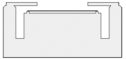
Le terme de piston, souvent ignoré, n'est pas le fruit de l'imagination de quiconque. Dans un interféromètre bien conçu, il peut constituer un atout fiable pour de nombreuses applications. Si ce miroir déformable peut sembler ésotérique, le concept est très utile, par exemple pour calibrer un modulateur de phase à cristaux liquides. Le cas optique est similaire : l'ouverture claire n'est pas liée à une phase fixe et les champs de franges réduisent l'efficacité de la valeur intégrée d'un gradient de phase.
Précision et degrés de liberté ouverts
Tout d'abord, qu'est-ce que j'entends par degrés de liberté ouverts? Il s'agit de degrés de liberté qui contribuent directement à l'erreur de mesure. Ils sont peut peuvent être étalonnés - et le sont généralement - mais ils représentent des sensibilités linéaires. Un exemple classique est le déplacement des micro-lentilles dans un réseau de micro-lentilles. S'il n'est pas correctement calibré, ce déplacement rend les capteurs Shack-Hartmann pratiquement inutiles pour les mesures précises du front d'onde.
Les sensibilités des pixels de la caméra sont-elles “ouvertes” ? Dans le cas des capteurs Shack-Hartmann, les sensibilités linéaires des détecteurs semblent ouvertes, puisqu'elles remodèlent individuellement les intensités enregistrées. Cependant, en supposant que ces sensibilités soient linéaires et constantes, elles s'annulent dans l'étalonnage déjà effectué pour les centres des spots.
Les interféromètres sont-ils nécessairement précis ? Non, évidemment. De nombreux facteurs contribuent à l'erreur totale. Cependant, comparé à la plupart des solutions de détection de front d'onde, les concepteurs de systèmes optiques ont un certain degré de contrôle. Chez Senslogic, où nous développons notre propre capteur Shack-Hartmann, nous comprenons la valeur de l'étalonnage de ces dispositifs et l'effort nécessaire pour le faire correctement. Cela dit, lorsqu'il s'agit de précision ultime, rien ne vaut une métrologie qui peut être tracée jusqu'à un seul élément de précision.
L'interféromètre à déphasage en est un parfait exemple - ou peut-être devrais-je dire a interféromètre à déphasage, pour souligner que le déphasage est une technique superposée à une configuration d'interféromètre spécifique.
Déphasage
Passons brièvement en revue la méthode du déphasage et ce qu'elle a de particulier. Pratiquement toutes les installations interférométriques peuvent être améliorées par le déphasage, ce qui signifie que l'un des deux chemins que la lumière peut emprunter ajoute une distance inférieure à la longueur d'onde bien connue afin de transformer l'analyse des franges en une simple équation pour la phase relative entre les chemins.
Le déphasage n'est en aucun cas une nouvelle technologie, et dans la littérature passée, vous trouverez des méthodes assez élaborées impliquant de nombreux pas de phase afin de surmonter les insuffisances de la technologie dominante disponible à l'époque. Cependant, le pas de phase de 90°, introduit dès le début, offre une telle annulation d'erreur intégrée que, pendant au moins deux décennies, il n'y avait aucune raison d'utiliser autre chose pour analyser une configuration d'interférence à deux faisceaux.
L'expression résultante pour la phase,
où l'indice indique le nombre de pas de 90° que nous avons effectués avec notre actionneur. A et B sont les amplitudes réelles des deux faisceaux qui interfèrent, réelles parce que nous avons déplacé la différence de phase entre eux dans la phase. Il est encore plus important de noter que, lorsque les intensités sont enregistrées sur une caméra, chaque pixel nous donne une des paires d'expressions ci-dessus à résoudre, où il suffit de diviser,
L'expression ci-dessus est maintenant exempte de A et de B. Il s'agit en fait d'un problème plus important qu'il n'y paraît à première vue, car A et B dépendent tous deux de la sensibilité des pixels de la caméra qui les a enregistrés à la position donnée, et ils ont maintenant disparu. Nous n'avons pas non plus mentionné que chacune des intensités peut avoir été enregistrée dans un laboratoire où il y a une source de lumière de fond. Cette contribution a disparu dans la différence entre les intensités au numérateur et au dénominateur.
Le pas de phase de 90° est parfois appliqué comme une mesure 4+1, où le déphasage (apparemment) redondant de 360° est mesuré. Aussi rudimentaire qu'elle puisse paraître, l'approche 4+1 supprime les non-linéarités de deuxième, voire de troisième ordre du détecteur et les erreurs d'échelle de l'actionneur. Le module PSI dans WaveMe propose à la fois la méthode des 4 images et celle des (4+1) images, qui, à défaut d'autre chose, peuvent être utilisées pour vérifier que les hypothèses que nous pouvons avoir concernant notre configuration sont correctes.
Avec le déphasage, nous devons avant tout nous assurer que les différences entre les intensités capturées ne reflètent que l'effet de notre actionneur, et comme les images sont enregistrées à des moments différents, toute variation temporelle apparaîtra comme une erreur. Il existe des méthodes qui capturent les quatre phases simultanément, mais cela nécessite une caméra très différente et l'analyse des erreurs sera également très différente. James C. Wyant est un partisan très respecté de cette approche.
Résumé
Avec ce discours technique, j'ai voulu éclairer certains points à prendre en compte lorsque l'on est confronté au choix d'utiliser un capteur Shack-Hartmann ou un interféromètre. Si vous optez pour le premier, il existe des produits à haute résolution sur le marché. Si la résolution n'est pas celle que vous recherchez, il n'y a pas grand-chose à faire, si ce n'est chercher une autre solution. Il en va de même si vous avez besoin du terme de piston, ou de la moyenne de la différence de longueur de chemin. Votre choix se porte alors sur l'interféromètre à déphasage. Si vous n'êtes pas satisfait de la résolution, choisissez une autre caméra. Vous avez le contrôle. Cela ne change rien à l'application. Il n'y a pas de nouvel étalonnage. Pour prendre un exemple de mon passé, il se trouve que j'ai utilisé ce qui se trouvait sur la table à ce moment-là, c'est-à-dire une caméra destinée à la vidéo (la différence n'est pas si grande), mais le fait est qu'avec une telle compensation intégrée, vous n'avez pas besoin de vous préoccuper beaucoup plus que de votre propre configuration optique.


Laisser un commentaire