


Calibration and Why it is Needed
The WaveMe toolbox has a rather exceptional calibration method that allows for much more flexible use of the Shack-Hartmann wavefront sensor. This tech talk will be about what it is and why it is different from what is available elsewhere. We will assume that you, the reader, are already familiar with the principles of the Shack-Hartmann wavefront sensor. However, most explanations one will find on the internet will not provide any numbers, I hope we can take a different view here.
A Simple Numerical Example
Let’s start with the typical placement accuracy of a micro-lens array, which is about 250 nanometres. For simplicity, let’s assume that all mirco lenses have the same placement error, including direction. This is a little silly example because we have only shifted the entire array 250nm. It does, however, help us to connect some of the configuration parameters of a sensor with the integrated wavefront. If we also assume that the distance between the array and the sensor is the same as the size of the aperture, then after integration of this displacement error we will have 250 nm wavefront error. If only half of the micro-lenses in the array are displaced by this amount, we will see half the wavefront error. This, however, is still a very large number relative the accuracy that we are aiming for.
But for Hartmann sensors, we must make the distinction between random and systematic errors. A 250nm systematic displacement, not that this is how we would interpret it, will becomes a 250nm tilt wavefront error (under our current model assumptions). If we instead have a 250nm random error, then error is becomes 250nm divided by the square root of the number of spots. This is often quite a good number. The point with this exercise is to emphasize how important it to control systematic errors when doing wavefront measurements with a Shack-Hartmann sensor.
Fine positions
While 250 nanometre sounds like a lot, even a mega-pixel sensor array will have a pixel size of several to sometimes north of 10 micrometres. Clearly, an accurate wavefront sensor needs to find the centre of light distribution with some accuracy.
There are several ways to do that, but a quite common method is to use the centroid, which sums the sampled intensity of a camera pixel multiplied by pixel coordinate and divided all by the sum of sampled pixel intensities. If our spots are large, meaning is intensity is varying slowly over the size of a pixel, this method is quite good. However, for small spot sizes, the centroid algorithm produces a large random-looking error.
Here’s something worth noting. When we focus on low-order wavefront errors, such as coma or astigmatism—which we often do—the numerical noise in centroid position usually has little impact, and the results remain quite good. This happens because the systematic error stays relatively small. Another important point about Shack-Hartmann sensor calibration is that we must keep systematic errors extremely small, matching the level of accuracy we aim to achieve.
Fine positions using templates
The Shack-Harmann module in WaveMe does not compute centroids. Instead, we use the “template” method so that we can analyze many spots with moderate camera resolutions. The template method requires that we figure out which model spot fits best to the current data. Using a model spot, the program produces a set of templates different spot positions within a pixel and its neighbors. And then, a little simplified, WaveMe correlates the current data with this template. Since the target application for WaveMe is day-to-day alignment work, the sensor will need to handle both collimated and divergent beams. Because of this, WaveMe optimizes the template in a background thread. But the story does not end here, in fact, it is actually just the beginning.
Calibration Methods
There are many ways to calibrate a Shack-Hartmann sensor. The best one depends how we want to use it. If the sensor is in a fixed setup, illuminated with a collimated beam a differential calibration may be more than enough. When the measured wavefront is less predictable, we need to reconsider this approach.
Differential Calibration
When it comes to selecting calibration methods, we may divide them into two, differential and absolute. When using the differential method, we would store the spot centers as a reference and present the wavefront “error” and the integrated deviation from this reference. If the reference was taken with plane wavefront, then our result is the actual wavefront illuminating the micro-lens array. If, however, we are measuring a divergent wavefront, several other systematic error contributions will appear that may easily dominate all other error sources. We’ll dive deeper into this topic later.
Absolute Calibration
Another calibration approach, which we can refer to as absolute calibration, uses spherical wavefronts, captured at different distances to the reference source. This base data set can then be (for example) interpolated into when generating a reference for the current source position. Here, we can quite immediately draw the conclusion that the common application of this data will be some sort of extrapolation and our model should therefore be a low-order polynomial. The advantage of this method is that spherical wavefronts are available at very high quality. Single mode fibres or proper pinholes will provide very high-quality spherical wavefronts. What they don’t provide is converging wavefronts, which means that when we use this method with converging wavefronts, the amount of extrapolation can be significant. For Shack-Hartmann sensors, there are limits how much of a converging wavefront we can measure anyway but still, this limits the useful range.
WaveMe – Synthetic Reference Calibration
WaveMe uses a different approach entirely, where the optical centres of the micro-lenses are extracted from the calibration information, in 3D, and a physical optics model is implemented to account the effects of the limited Fresnel number. The only assumption is that the array is flat, but beyond that, it may be placed at mechanical tolerances. No alignment of the array is needed.
The relaxed alignment requirement of the micro-lens array can be quite an advantage because even small differential screws can be several millimetres in diameter and over a centimetre in length. This prevents any cost-efficient integration of sensor and lens arrays as a single unit. This enables extremely compact and still very accurate solutions.
Continuous reference generation and optimization
WaveMe assumes that the camera is always streaming images. This information is analyzed by an independent thread to extract the source position, and using this information, the Shack-Hartmann module creates its own spot position reference data based on the physical optics model and a virtual ideal point source which now may be at any position, generating both diverging, collimated, or converging (virtual) reference wavefronts. The virtual sources may also have any angle of incidence.
This method could be thought of as an absolute calibration, but it is more descriptive to think of it as a vritual source calibration. The aforementioned absolute calibration uses interpolated or extrapolated results from a larger number of explicit spot position measurements while the latter, infers a single set of optical centers for the microlenses from a larger number or measurements. The difference may seem subtle, but it is not. WaveMe infers micro-lens positions and a physical optics model that explains all the data that are provided to it during the calibration process. In relative terms, the difficulty is moved to the calibration process while the application of the model is, at least numerically speaking, relatively simple and intrinsically covers all application cases. This is a choice that better fits the target application where no assumption of alignment of the incident wavefront can be expected.
Enabling Technology
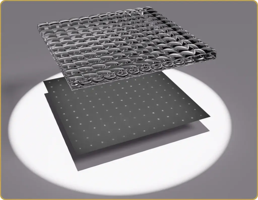
One advantage of synthetic reference calibration is that it supports applications where there’s no space for a kinematic mount or mechanical adjustments. For example, one can place micro-lens array on a PCB atop a CMOS sensor using a pick-and-place machine. The result is a compact and robust Shack-Hartmann sensor at an unmatched price point, with the mathematics taking care of the calibration effects due to misalignment.
While this specific solution isn’t within the current focus at Sensolgic, we are actively exploring other applications of this technology. If you find the camera integrated solution interesting, please contact us. There are many aspects of the technology that Senslogic doesn’t have the resources to explore at the moment, but we are open to a cooperation.
Comparing with Other Implementations
Browsing the internet for Shack-Hartmann calibration and measurement techniques, one will encounter the concept of Area of Interest (AOI) or Region of Interest (ROI), which defines a set of square patches roughly aligned with the centers of spot positions. We don’t use these concepts in WaveMe. While, arguably, they work in a static application, the dynamic use case for WaveMe prevents it entirely.
WaveMe is based around the assumption of an image stream. When the Shack-Hartmann module is activated, it will try to identify the existence of a spot pattern. This pattern can have any rotation and the range of accepted spot spacings is larger than most practical wavefront sensing conditions. Once a spot pattern is identified, spots are enumerated and a process adapting a spot model to the current data is started in an independent thread. Once the spots have been enumerated, the following images are processed using the spot tracking.
Since there is no fixed space that the spot pattern must fit into, there is no explicit dynamic range for the sensor. There will, however, be one in the sense that when we the sensor is moved to close to the source, the relative sizes of the spots will change too much, and the accuracy will be somewhat degraded.
Another reason that WaveMe does not use a fixed grid to localize the spot pattern is that the source position is not assumed to be known. The wavefront can illuminate the sensor from a wide range of directions and distances. Fixed AOI’s would be too much of a limitation and the requirement of adapting them to the current spot positions is not acceptable for when using a sensor intended for interactive optical alignment, which is the target application for this module and WaveMe in general. After all, it is supposed to be point-and-shoot.


Leave a Reply