


Technology continues to advance, and so do wavefront sensors. One notable improvement has been in wavefront sampling density. Examples of such sensors include the HASO LIFT sensors from Imagine Optics and the QWLSI sensor by Phasics. Each uses a different technique to achieve higher sampling density.
The LIFT technique—short for Linearized Focal-plane Technique—is a modern take on a method once used to maintain focus in CD and DVD players. In that older application, a cylindrical lens introduced on-axis astigmatism into the reflected beam. When the disk was in focus, a quadrant detector would show equal signals in two opposing cells. If out of focus, the difference in signals (including its sign) could be used for feedback.
In a similar spirit, the LIFT technique adds on-axis astigmatism but samples the focal point at much higher resolution. This allows it to resolve far more wavefront terms than simple curvature.
Phasics’ QWLSI approach, by contrast, uses interference to create a two-dimensional fringe pattern. With Fourier fringe analysis, it extracts two wavefront gradients, which are then integrated to reconstruct the wavefront.
Interferometry, accuracy & resolution
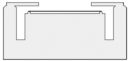
Although LIFT and QWLSI may seem to have nothing in common, they actually do. Neither can measure absolute deflection on the deformable mirror system shown below. Does that matter? That depends on the goal. What both methods can do quite well is measure the shape of the mirror based on the signal—something that is often more than sufficient. However, in the example shown below, where the entire mirror isn’t visible, we’re out of luck.
The piston term—often ignored—is not a figment of anyone’s imagination. In a well-designed interferometer, it can be a reliable asset for many applications. While this deformable mirror may seem esoteric, the concept is quite useful—for example, in calibrating a liquid crystal phase modulator. The optical case is similar: the clear aperture isn’t tied to a fixed phase, and fringe fields reduce the effectiveness of relying on the integrated value of a phase gradient.
Accuracy and open degrees of freedom
First, what do I mean by open degrees of freedom? These are degrees of freedom that directly contribute to measurement error. They can be calibrated—and usually are—but they represent linear sensitivities. A classic example is the displacement of micro-lenses in a micro-lens array. Unless properly calibrated, this displacement renders Shack-Hartmann sensors practically useless for accurate wavefront measurements.
Are camera pixel sensitivities “open”? In the case of Shack-Hartmann sensors, the linear detector sensitivities seem open, since they individually reshape the recorded intensities. However, assuming those sensitivities are linear and constant, they cancel out in the calibration already done for spot centers.
Are interferometers necessarily accurate? No—obviously not. Many factors contribute to total error. Still, compared to most wavefront sensing solutions, optical system designers have a degree of control. At Senslogic, where we develop our own Shack-Hartmann sensor, we understand the value of calibrating these devices—and the effort that goes into doing it right. That said, when it comes to ultimate accuracy, nothing beats metrology that can be traced back to a single precision element.
A perfect example of that is the phase-shifting interferometer—or perhaps I should say a phase-shifting interferometer, to emphasize that phase-shifting is a technique layered onto a specific interferometer configuration.
Phase-shifting
Let’s do a short review of the phase-shifting method, and what’s so special about it. Practically any interferometric setup can be augmented by phase-shifting, which means that one of the two paths the light can take adds another, and well known sub-wavelength distance in order to turn fringe analysis into a simple equation for the relative phase between the paths.
Phase-shifting is by no means a new technology, and in the past literature you will find quite elaborate methods involving many phase steps in order to overcome the shortcomings of the prevalent technology available at the time. However, the 90° phase step, introduced from the very beginning, offers so much built-in error cancellation that, for at least two decades, there was no reason to use anything else to analyze a two-beam interference setups.
The resulting expression for the phase,
where the index denotes the number of 90° steps we have done with our actuator. A and B are the real amplitudes of the two interfering beams, real because we have moved the phase difference between them into the phase. Even more important is it to note that, when the intensities are recorded on a camera, each pixel gives us one of the above pair of expressions to solve, where we just divide,
The above expression is now free from both A and B. This is actually a bigger deal that may be immediately obvious because both A and B depend on the sensitivity of the camera pixels that happens to record them at the given position, and now they are gone. What we also didn’t mention that each of the intensities may have been recorded in a lab where there is a background light source. This contribution disappeared in the difference between intensities in both numerator and denominator.
The 90° phase-stepping is sometimes applied as a 4+1 measurement, where the (seemingly) redundant phase shift of 360&\deg; is measured. Rudantant as it may seem, the 4+1 approach suppresses second and even 3rd order detector non-linearities and actuator scale errors. The PSI module in WaveMe offers both the 4-image and (4+1) image methods, which, if not for anything else, can be used to verify that the assumption we may have regarding our setup are correct.
With phase-shifting, we primarily need to make sure that the differences between the captured intensities only reflect the effect of our actuator, and since the images are recorded at different times, any time variation will appear as an error. There are methods that capture all the four phases simultaneously, but this requires a quite different camera and the error analysis will also look quite different. James C. Wyant is a much respected proponent of this approach.
Summary
With this tech-talk, I wanted to illuminate some things to consider when facing the choice of using a Shack-Hartmann sensor or an interferometer. If you choose the former, there are high-resolution products on the market. If the resolution is not what you are looking for, there isn’t much you can do except looking for another solution. The same goes if you need the piston term, or the average of the path length difference. Your choice is then the phase-shifting interferometer. If you’re not happy with the resolution, pick another camera. You are in control. This changes nothing in the application. No new calibration. Just to take an example from my own past, where I happened to use whatever was at the table at the moment, which was a camera intended for video (not that it’s such a big difference), but the point is, with so much built-in compensation, you don’t have to care all that much beyond your own optical setup.


Leave a Reply