


The Smartt interferometer or its evolution, the Phase-shifting point diffraction interferometer is probably the most accurate one can make, and it is not even expensive. It has its limitation, doesn’t everything, such as that we need a focus to create a reference wave with a pinhole. If the focus is at a high numerical aperture, the pinhole may be really small so one needs to consider the possibility that it may evaporate when we actually want to use it. But all that can be overcome with a little careful engineering, particularly with pulsed sources such as Excimer or Q-switched lasers. For micron-sized pinholes, there is probably no problem because we still need to adjust the exposure to record the interferogram on a camera, which are usually very sensitive.
Another drawback is that it is not a flexible interferometer. It is more of a custom tool made for specific systems. That said, it is not expensive to make, a pinhole, an actuator and another (off-the-shelf) pinhole that may even be modified at your local precision mechanics shop. This is what I did the first time I needed one. With less than 5k to 8k of actuator and pinholes, and some software we have a tool that is at least lambda/200 or even lambda/300 accurate and lambda/500 to lambda/2000 stable, depending on aperture size and thermal environment where the interferometer is located.
Accuracy
This level of accuracy cannot be acquired from any commercial source that I know of. Probably, we should also qualify the claim of lambda/300 accuracy. Since the point diffraction interferometer creates its reference using whatever wavefront is being measured, the reference will only be a perfectly spherical wave if the pinhole is illuminated with a perfectly spherical wave. In reality, it is more of a 3-3.5% accurate interferometer for optics at the diffraction limit or below. Some aberrations are suppressed more (like spherical or power) and others less (like coma). So the 3-3.5% number is akin to something like an ensemble average, and since the RMS value for wavefront at the Rayleigh criterion is of the order of 0.07 to 0.08 (depending on the wavefront), we will get down to something like 1/0.075/0.035 = 380. In practice, there is some operator variation when aligning and focusing on the pinhole, and some other things.
In practice, one can see the effects of the deformation of lens elements when mounted with ever so slightly different mechanical force. This interferometer feels almost like a mathematical tool. Don’t get me wrong, I do like Shack-Hartmann sensors. When used for the right job, there’s nothing better, but when we try to push them below 10nm RMS, a lot of control over systematic errors is required. With the point diffraction interferometer, there are practically no questions. What you see is what you’ve got.
The phase-shifting is done with a coarse (Ronchi-type) grating and the main design choice is if the wavefront is to be measured through the 0th or the 1st diffraction order. We can choose to measure with or without a fringe projection lens, but if we choose not to have one, it becomes difficult to identify the pupil which defines the optical system being measured. Therefore, it is preferable to have a fringe projection optic but that of course forces us to answer the question about the measurement error added by the optics between the pinhole and the camera.
If we choose to measure through the 0th order with a high fringe count (which sets the resolution of this instrument), we will have to calibrate the fringe projection using two pinholes, which is somewhat difficult because we now must put two foci through two pinholes at the same time. This pair of pinholes need to be custom-made if we need the highest possible wavefront accuracy. On the other hand, We will have pretty accurate uncalibrated results, especially if the fringe projection optic is corrected for coma, well-aligned and the fringe count (resolution of the interferometer) is not too high, say 50-70 fringes.
Trade-offs
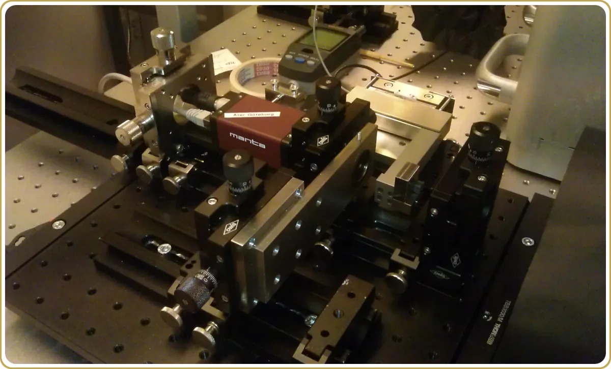
If the goal is the highest possible resolution and simple fringe projection optics, we can measure through the 1st order. The advantage of this is that we can get close to 100 percent fringe contrast, which looks nice but is really not that critical, but what is more important, the calibration is done using a slit isolating the 0th and 1st diffraction order which are used during the measurement. This aperture is very simple to make or buy as an off-the-shelf component. But in this case, we have to calibrate. The interferometer shown here is of this type. The fringe projection lens is just a plano-convex singlet with a focal length that adapts the pupil image size to the camera. The simple calibration takes care of the linear coma (and conical diffraction effects if the grating is in the converging beam) and as long as we don’t move the pinhole, we don’t have to recalibrate, which is why it is all on its own table that can be moved over the field. When needed, the calibration is a one-minute procedure.
This is with without doubt, my favorite interferometer setup. There are things one has to do correctly, such as the to make sure the grooves of the transmission grating are straight. In this particular case, the grating was manufactured at Chalmers MC2 in a mono-silicon wafer etched using the Bosh process (but there are other ways), and as a little kicker, one can verify the straightness of the grooves using the interferometer without touching the grating.
About the image
This particular setup was measuring a 60kg demagnifying relay with 600 mm working distance at NA of about 0.05. There was no practical way to access its Fourier plane which is why the interferometer is entirely outside of this optical system.
To finish with an anecdote, that 60 kg relay ended up on that optical table because its manufacturer could not verify its performance. There was reason to believe it was misaligned but what and how much, nobody knew. After a 15 minute scan over the field, a perfectly straight line over the field in Z6 appeared at about 150 milli waves at the endpoints. Classical. A little testing in Zemax revealed moving the image 0.8mm by tilting a mirror should reverse the linear Z6 so that was what we did. Bingo. No more linear Z6. As if mathematically cancelled. This is why I love this interferometer. It is such a clean tool to work with.