About This Tech-Talk
Spatial light modulators (SLMs) are active optical components that can alter a light beam’s amplitude, phase, or polarization. For this tech-talk, I’ll focus on a specific subset: those that achieve this using a pixelated, two-dimensional array. While this doesn’t cover all types of SLMs, it’s a sufficiently large and interesting category to explore. Because this blog focuses on system integrators, I’ll also highlight key considerations if you decide to incorporate an SLM into your system.
Reflective or Tranmissive
To begin with, we have two major sub classes, reflective and transmissive. Most of the industrially interesting SLMs are the reflective type. The reason for this is simple. High performing devices require a CMOS wafer to distribute the data over the device. The simplest way to achieve that is to put a metallic layer directly on top of a wafer. It is possible to arrange an optically transmissive surface that can distribute an electric signal but that implies free electrons and those tend to interact with the transmitted light. The trade-off that this implies typically affects device speed or optical transmission.
That said, you can still find many technically interesting products that use this principle in both consumer applications (such as LCD displays and some LCoS-based projects) and industrial settings.
Reflective Amplitude SLMs
This is a major class of spatial light modulators. Notably, we find the The Texas Instruments DLP in this class. Even if this type of SLMs alter the phase of the reflected light, they are not used as such. Let me explain. The DLP is a purely reflective micro-mirror device where each micro-mirror can have only two stable states altering between plus or minus 12 degrees along its diagonal, although the angle can differ between various types. Each point on the surface of this device alters the phase of the light by introducing an optical path difference, but since these phases are not independent, we can only observer the net effect of a small, tilted mirror.
There are other SLMs operating along the same optical principle, such as the IPMS analog tilt mirror SLM. Since the tilt-mirror devices are overall phase neutral, they rely on the imaging system to express their intended effect. Without it, they just look like a rough reflecting surface. With a properly designed projection system, they turn into high performing pattern generating systems that cannot be distinguished from high-quality binary masks.
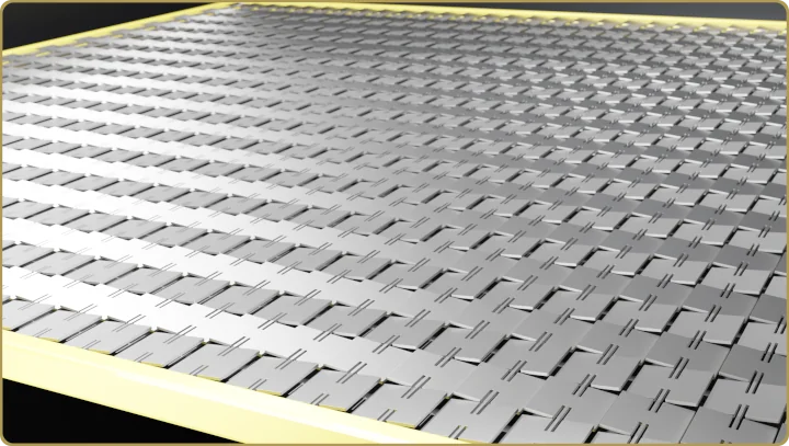
The analog tilt-mirror devices are simple to calibrate and simple to use but require an Excimer laser to reach their true potential. There are, however, some properties that a tilted mirror in the image plane brings which are worth to keep in mind. The tilt of an isolated mirror can never hidden by the optical system even if the projection optics is not even close to resolving the micro-mirror. This can sometimes be used to properly set focus, possibly even the most sensitive way to do it without an interferometer or wavefront sensor but probably only useful at lower resolutions.
Fourier theory to the rescue
In order to use a tilt-mirror device of this type for high-end applications, the mirror tilt has to be alternating (as in the figure above). The projection optics will then cancel the phase. Generally speaking, these devices are best understood using Fourier theory.
Here’s an example: A device having flat mirrors has infinite contrast, one just has to tilt the mirrors to the correct angle. The tilted plate (or mirror) has a reflection pattern given by the sinc-function and the zero of that sinc is the correct angle for infinite contrast. What happens when we use partially coherent illumination, and the SLM is illuminated with a range of incident angles? Does that mean the contrast is degraded with partially coherent illumination? If we stick with the sinc-picture, we may be led to believe that it is impossible to arrange an optimal tilt angle since we cannot simultaneously adapt the one tilt angle to a -range- of incident angles. If we go with the Fourier approach instead, the array illuminated at zero incidence reflects all light along the normal. The effect of the tilt is represented as a set of diffraction modes which are not going to be transmitted through the pupil. For any off-axis plane wave, the reflected light is just a shifted replica of the on-axis pattern. If the first one had infinite contrast (when viewed through the projection optics), so does the replica. The Fourier approach gives the right answer.
Common device defects
MEMS devices are never perfectly flat. When the polished surface they are made on top of is resolved, there is a mechanical release of forces which adds a short-range vertical displacement. This introduces a partially developed speckle and other effects. It sets the limit to image quality when using these devices. Not all manufacturers are forthcoming with a specification regarding these effects. For example, I have not been able to find it for the Ti DLP. However, some limits to this parameter are given by diffraction efficiency. Since the DLP must overlay many images in order to generate a grayscale, partially developed speckle should not contribute significantly to the degradation of image quality when using these devices.
With time, especially when using short wavelengths, the top surface can suffer some annealing and compactification that leads to some curling of the mirrors. For the DLP, this has an insignificant effect on image quality due to the large tilt. For the analogue devices, this is probably the property that sets the usable lifetime of the device. It is visible as a contrast degradation but affects other important imaging properties, like focus sensitivity.
Linear Amplitude SLMs
The linear or one-dimensional modulators probably deserve their own page but I’ll try to squeeze in some of the essentials here by talking about two vastly different devices. One is the Silicon Light Machines Grating Light Valve, or GLV for short. The other is the Fraunhofer IPMS 8k show in this document.
What makes the 1D modulators interesting is they can use a continuous or quasi-continuous laser source. In the case of the GLV, it can even use a Q-switched laser. This is very attractive from a system cost perspective. Even though the repetition frequency of the GLV is on the high side for a Q-switched laser, there are still good options available. The main drawback of the GLV is they way it generates gray-scale.
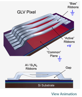
The gray-scale is generated by creating a grating with a variable depth, and hence, a variable magnitude of diffracted light. This device can be used in both 0th and 1st order but has significantly better contract in 1st order. Some variants of the device combine two ribbons to form a pixel, while other use 6 or 3 ribbon pairs. This does not have any significant effect on the optical image properties.
What is essential to keep in mind, however, is that this approach couples the reflected amplitude and phase, which for lithography is critical because it causes a focus sensitivty if the device is used for gray-scaling (which is mostly the case). Another consequence, perhaps not all that critical, is that the reflection minimum cannot be calibrated if the device is used in 0th order. One might wonder, how do we calibration a SLM that does not reflect any, or very little light? Let us just say that the tilt-mirror SLM can be easily calibrated while the GLV survives this simply by not being very sensitive when operated close to zero reflected amplitude. As a seque to Fraunhofer device we will mention that the GLV needs to be illuminated by a narrow line, 5-10 micron thick. This means that we must consider the peak power density when we use this device.
So how does the Fraunhofer devcie solve this? This device was developed to handle high-power continuous sources from the start. Therefore, the device is optically flat over its entire 80×2 mm2 surface. To make use of this, the SLM must be placed before or after best focus. To avoid to much cylindrical optics, an image free from astigmatism can be re-established by inserting one or two tilted parallel plates.
Since this device uses tilt-mirrors, it is phase neutral and does not display any through-focus effects when used as a gray-scaling SLM. Before we move on to the next section, it should be mentioned at least somewhere on the interenet, this modulator was designed for a 2MHz frame rate, not 1MHz as the linked document (and the publication about it) claims. The reason we can get away with driving a device above its nominal resonance frequency is that the modulator was designed for a quite low Q-factor of about 1 and a gray-scaling device cannot resolve single pixels anyway. Usually, a good design typically resolves 3 to 4 pixels, depending how much we value image quality. Those two design choices allowed Micronic to drive this modulator at 2MHz. With a 1.25um pixel (in that direction) resulted in a 2.5 m/s write speed. It was quite something to see.
Reflective Phase SLMs
Reflective phase SLMs create a path length difference mostly in two ways. Either by displacing the reflecting surface or by locally changing the refractive index in order to generate a path-length difference. The former would describe spatial light modulators like the RealHolo, the Texas Instruments PLM or Silicon Light Machines PLV. In terms of technical potential, the RealHolo clearly stands out in the MEMS crowd.
Liquid Crystal on Silicon – LCoS
Another popular phase SLM technology is Liquid Crystal on Silicon (LCoS). These micro-displays rely on a fairly complex stack of technologies, including a CMOS backplane, metallic pixel layer, top and bottom alignment layers for the liquid crystal, an Indium Tin Oxide (ITO) layer to generate the electric field across the liquid crystal, and a cover glass to hold the ITO. Despite this complexity, manufacturers can produce LCoS panels in large volumes with high yields and minimal pixel defects.
LCoS panels offer several advantages, including robustness. However, they also have drawbacks, such as polarization dependence. Additionally, the liquid crystal layer’s thickness, determined by the wavelength the SLM is designed for, limits the modulator’s effective resolution. This limitation arises from the nature of electric fields, which tend to diverge as they spread from their source. LCoS panels are essentially densely packed transparent capacitors, and when the lateral size of each capacitor is smaller than the distance between its plates, the electric field spills over into neighboring pixels, creating cross-talk. In the LCoS industry, this phenomenon is known as fringe-field effects. It causes both unwanted polarization effects and disclinations. Before we jump into MEMS SLMs, we have to mention one major advantage which is that you can buy them today from companies like Hamamatsu or Holoeye Photonics.
MEMS Piston Mirror Arrays
Even if the piston-MEMS devices are not as rare as unicorns, you will not easily spot one in the wild. That said, they do exist and if Texas Instruments eventually releases the PLM, they may in fact become quite common. Piston devices are really flexible from the optical point of view. There are no polarization effects to speak of. No wavelength dependence as long as we illuminate with one wavelength at the time. They are fast and the phase is stable. With LCoS, one has to frequently change the polarity of the driving voltage in order to prevent degradation of the liquid crystal. None of that stuff here. 360 degree phase modulation and no cross talk to talk about. Great. Can I have a bunch? There is one problem, which is equally valid for the LCoS panels, how to you decide which phase to set on each illuminated pixel?
Image generation with phase-only devices
Usually, we go to the Gerchberg-Saxton algorithm when we need to solve this problem. It is especially useful in visual applications, where the brain renders the result more palatable. One great advantagle of phase-modulating devices is that we don’t need optics. Illuminate with a wide enough beam and you have a projector from two parts, lightsource and SLM. The wavelength and by the pixel size limits its angular extent, but if that is enough, we are done. Otherwise, we may use a Galilean telescope to provide the desired magnification.
For lithography, where image quality is everything, we have to control the reflected phase of the light. If we fail to do that over a long range, our objects move through focus. Failure to do that over a short range also adds speckle to our objects which, in addition, increase with the aberrations of our projection optics.
There is, however, one more thing to consider. How will we decide the phase to set for each pixel? Phase retrieval methods are iterative and, to my knowledge, return a random projected phase. The direct methods that I know use neural networks but I have not seen what image quality we can expect of them. I would expect that the neural network approach will at best reproduce the results of the phase-retrieval methods used to train it. Consequently, I would expect those methods to generate a random phase.
Some theory fundamentals
On the topic of generating high quality patterns with phase-only modulators, we must at least identify two cases, one which is the linear mapping case, and the other, a non-linear mapping. The linear mapping case corresponds to the linear mapping between modulator and image amplitude of coherent imaging, while the non-linear case applies to partially coherent imaging.
For coherent imaging, we know that the image amplitude is a linear “function” of the reflected amplitude,
And when P represents a discrete device, we can turn the integral to a sum by integrating over the “pixels”,
There are details to this that I think we can skip for the moment. However, we know that one way or another, we can inverse this relation,
Practically speaking, the inverse of H is usually a pseudo-inverse and so on. This is not the point. However, even for the simple case where the impulse response H is real (meaning zero imaginary part), and the amplitude we are looking to solve for is also real, the solution (p) is then real. Not exactly a great solution for a piston device.
Pistons need a mapping to the complex unit circle
So, then we need a way to transform a real vector p (having NxM elements, where NxM is the size of our SLM) into a vector,
where the vector h has the same size as p. We want the heights, h, to have the property that,
meaning, we want want to cancel the imaginary part using the optical system. Now, it’s not my point to turn this blog into a math paper, but a well-designed image system intended for gray-scaling will leave a fair amount of room for solutions h that closely match the images generated by the mapping Hp.
For linear mappings, or coherent systems in other words, there is quite a lot we can do to find a distribution of piston phases, without combining (say) 4 pixels to create an effective gray pixel, which would lead to 4 times writing capacity loss. We would need to dive into lots more math to describe the procuess fully, so maybe another time.
When the Sky is Not the Limit SLM
The piston modulator applied to lithography is the ultimate modulator for those who want to push sub-wavelength resolution beyond its otherwise practical limits, but it does come at a cost. Here’s the point. A piston modulator can project any phase and amplitude (in relative terms) but for lithography, we actually do not want any amplitude. We want the image to have a constant phase over the entire image because a phase variation is a variation of feature dimensions or placement through focus, and we absolutely don’t want that. This means that we have to spend time in order to find a solution that constrains that particular degree of freedom of this modulator.
To both have the cake and eat it, Micronic invented a tilt-mirror design which included a quarter wavelength step over one half of the mirror. The result was an image amplitude that could reach a (relative) range of -1 to 1 and zero phase variation. All the good stuff that you needed the piston mirror for without the work. The downside was a reduction in reflectivity of the device, which for an application that included an Excimer laser was not an issue. Strictly speaking, there may be 2D topologies that this modulator cannot deal with in a single image. Nevertheless, ASML decided to use this solution for their direct-write behemoth. Unfortunately, ASML never released this product. To my knowledge, this is the largest SLM designed and fabricated to date. 11 million analogue-tilt 8 micron mirrors and 6 kHz image repetition rate. You can find a nice image SEM image of it here.
Want to Know More
If you want to know more, feel free to contact me through the contact page or simply drop and email to [email protected]. I like talking SLMs. You can also leave a comment right here.




Leave a Reply