


Introduction to Pattern Generators
The Ti DLP is becoming a major force in maskless lithography. Even though it is an odd tool for this task, it has qualities that more than enough compensate for its drawbacks. To explain what I mean, let’s go back a little.
Maskless lithography refers to an approach where using a photomask becomes economically impractical. Why? Because the volume and value of the objects we produce don’t justify the high cost of creating a mask. It is also about making more than just one object. Typically, the volumes are more than just one and we expect minute write times, not hours. This has many implications that I will not cover such as, for example, how much time we can spend on the data preparation. This tech talk is about the optical side of things.
Even when we focus on optics only, there will be differences between maskless and a mask writer. Both do, superficially, the same thing, they write a pattern on a surface covered with a photo-sensitive material. The difference is that the mask-writer typically targets significantly higher image quality and the volume is one pattern per object, which we typically refer to as a photomask. We have time to adapt the data to the projection system and adapt the projection system to the data, although this is rarely, if ever, used. Available time is usually one to several hours while for the maskless application, it is one or several minutes. There is no time to adapt anything.
Imaging Theory Principles
Every pattern generator requires an active optical element, and the choice is not only a matter of technology and practicality. However, no matter the choice, we can take for granted that the projected image using this element is much smaller than the size of the photo-sensitive surface we intend to expose with a pattern. Therefore, every pattern generator uses some sort of scanning.
The choice of pattern generator also affects ultimate resolution. Scanning the workpiece with a spot of light, which we move with an acousto-optical deflector, results in incoherent image formation because we can only add intensity over time. If the modulator exposes a two-dimensional object, the imaging becomes coherent or partially coherent. We can now add or subtract amplitude, which limits resolution to a quarter of the wavelength. However, even if we use simpler modulators that don’t modulate the phase, resolutions below half of the wavelength are possible even without advanced illumination. I covered some details of this in an earlier tech-talk.
The DLP – An Unexpected Champion
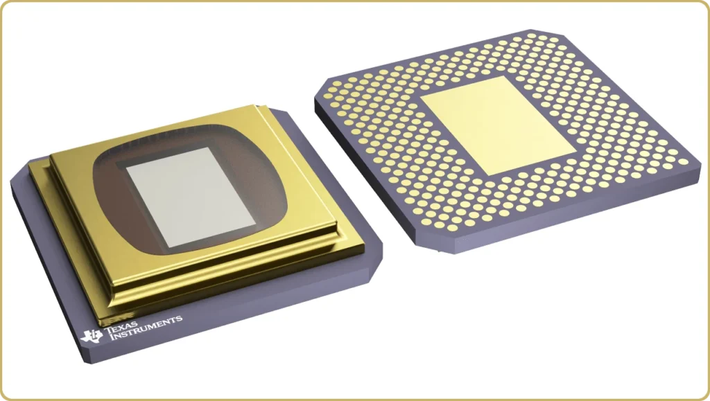
From a pure imaging theory point-of-view, the DLP is the strange kid on the block. Pattern generators need to create gray-scale images and the TI-DLP is a binary device. The light source is of prime importance for any imaging system. This is true -with interest- for a pattern generator. Texas Instruments designed the DLP for the arc lamp. We usually do not see this light source with SLMs because of etendue problems. For SLMs, the preferred light source is the excimer laser.
Origins and Limitations of the DLP
For someone like myself, who started out in the KrF – tilt-mirror camp, the DLP appeared to be a poor choice. It doesn’t have the same limit resolution since the implied gray-scaling method somewhat degrades the effects of partial coherence. However, all of that which seemed so important when optical mask writers were the rage, has gone by the way of the dodo bird two decades later.
The Changing Landscape of Pattern Generators
The race for pattern generators today is no longer resolution. Optical pattern generators write lost this battle to EBeam many years ago. The battle is now in the field of write capacity and price where the DLP has established a foothold that may be impossible to break. In this segment, the resolutions are moderate. Usually, not even smaller than the wavelength. The value of the exposed wafers will no longer cover the cost of an Excimer laser. Well, strictly speaking they might but the value of the masks will not cover the cost of developing such a machine.
Light Sources and Pattern Generators
We cannot overstate the importance of the light source for any optical pattern generator. The excimer laser generates hundreds of thousands of independent modes in a single 10 nanosecond pulse, and in doing so, it solves pretty much all the problems we encounter when designing a tool for a continuously moving workpiece. It fits perfectly the high-end mask-writer application with a two-dimensional modulator. It’s a match made in heaven because in heaven we don’t care about cost.
What are the alternatives then? We need independent photons to create spatial in-coherence, and these photons to fit into a small etendue. And to add insult to injury, we need a pulsed source so that it can freeze an image onto a moving workpiece. Let me sum this up. This light source does not exist. If we exclude the Excimer, we will have to compromise something. Available dose, or resolution (although not that much), or speed.
A Misfit with Traditional Light Sources
The DLP projector and the traditional lithography shop had one thing in common, the high-pressure arc lamp. But the similarity ends right here. The Mercury lamp was perfect for a large, high-resolution mask. Even after the Mask Maker’s Holiday, the numerical apertures combined with the size of the illuminated field, the “size” of the light source was still a good fit for a mask while it is a terrible fit for a SLM. With size of the light, I am of course referring to étendue, but that essentially means size or extent so we’ll go with it.
The laser is king in the SLM – Optical Lithography world, at least it used to be. Before we can dive deeper with DLP, I must digress a little. We need to talk about gray scaling.
Revisiting Gray Scaling and Resolution Limits
With analog mirror array SLMs, presumed to be 2D, gray scaling is done in the pupil, using it as a spatial low-pass filter. The degree of filtering can vary depending on how we want to the imaging system to behave close to the resolution limit (mostly). The filtering factor is usually parametrized as a ratio of the numerical aperture and the angular distance between the diffraction modes of the mirror array. Choosing this factor as one-third or a quarter of the fundamental diffraction angle (wavelength divided by mirror period) is usually a good choice, although both smaller and large ratios can be motivated, but values larger than one cannot ever be motivated because that destroys gray scaling through interference.
Analog Mirror Arrays vs. DLP
However, with the DLP, the plot thickens. For analogue devices, size of the light source that can be accepted by the projection system scales the aforementioned ratio squared times number of pixels. Why only the number pixels matter is because the numerical aperture scales inversely with pixel size while the size of the field is proportional to the pixel size and so the pixel size factors out. (please forgive the simplification implied by equating étendue with the pixel count. There is a dimensional error here since étendue is an area times a solid angle of the light cone and the inverse length which provides the numerical compensation is hidden inside the light cone together with the wavelength. However, we are comparing different technologies at a fixed wavelength. Hence the shortcut)
Here, the DLP offers an interesting twist. If the tilt angle, pixel size and wavelength match, the DLP may behave like a blazed grating with good diffraction efficiency. White areas in the pattern will look uniform white, and black will be uniform black even when the aperture includes higher array diffraction orders, and the shape of the mirrors will only be revealed in the transition regions. The system numerical aperture can now be opened up to a ratio above one and the device will now reveal the shape of the pixels in the transition regions. This is a small complication that can easily be solved inside the procedure used to generate gray scale.
The Future of Maskless Lithography: A New Era for DLP
So what’s going on here? Why is this relevant? The reason this the excitement is because the projection system now accepts a light source with a much larger size (étendue). Can we use the I-lamp again? I guess, but it’s even better. it becomes viable to drop the laser altogether and use a UV-LED.
DLP – A Write Capacity Game Changer
Two key factors make this exciting. First, we need a partially coherent light source for the DLP. This is costly and complex to create with laser diodes. It requires numerous LDs, fibers, and a lot of patience. LEDs, on the other hand, are multi-mode surface emitters. They’ve had one major drawback, their etendue is too large to fit normal SLMs. However, the DLP allows us to drastically over-size the numerical aperture and cover up the drawbacks with its multi-pass power, allowing much more light through. And if (or when) Texas Instruments releases the 4096 x 2160 UV modulator, it’ll solidify DLP as the ultimate solution for maskless writing. Let’s hope they don’t miss the blaze condition for 365 nm (by much). The current DLP9000XUV is already setting the stage, offering unmatched write capacity with an affordable light source. Figuratively speaking, this “strange kid on the block” will leave all other solutions in the dust.
Final Words
The DLP together with a UV-LED is undoubtedly a very interesting choice for the maskless application, one that will be increasing attractive with the projected development of DLP technology. That said, there are still both design challenges and production challenges such as how to adapt the aspect ratio of the LED to the modulator, preserve etendue, set design targets for the projection optics that match the system requirements, and more. For all those topics, you can find support here at Senslogic. You are welcome to schedule a free initial consultation.


Leave a Reply